Bill of Materials
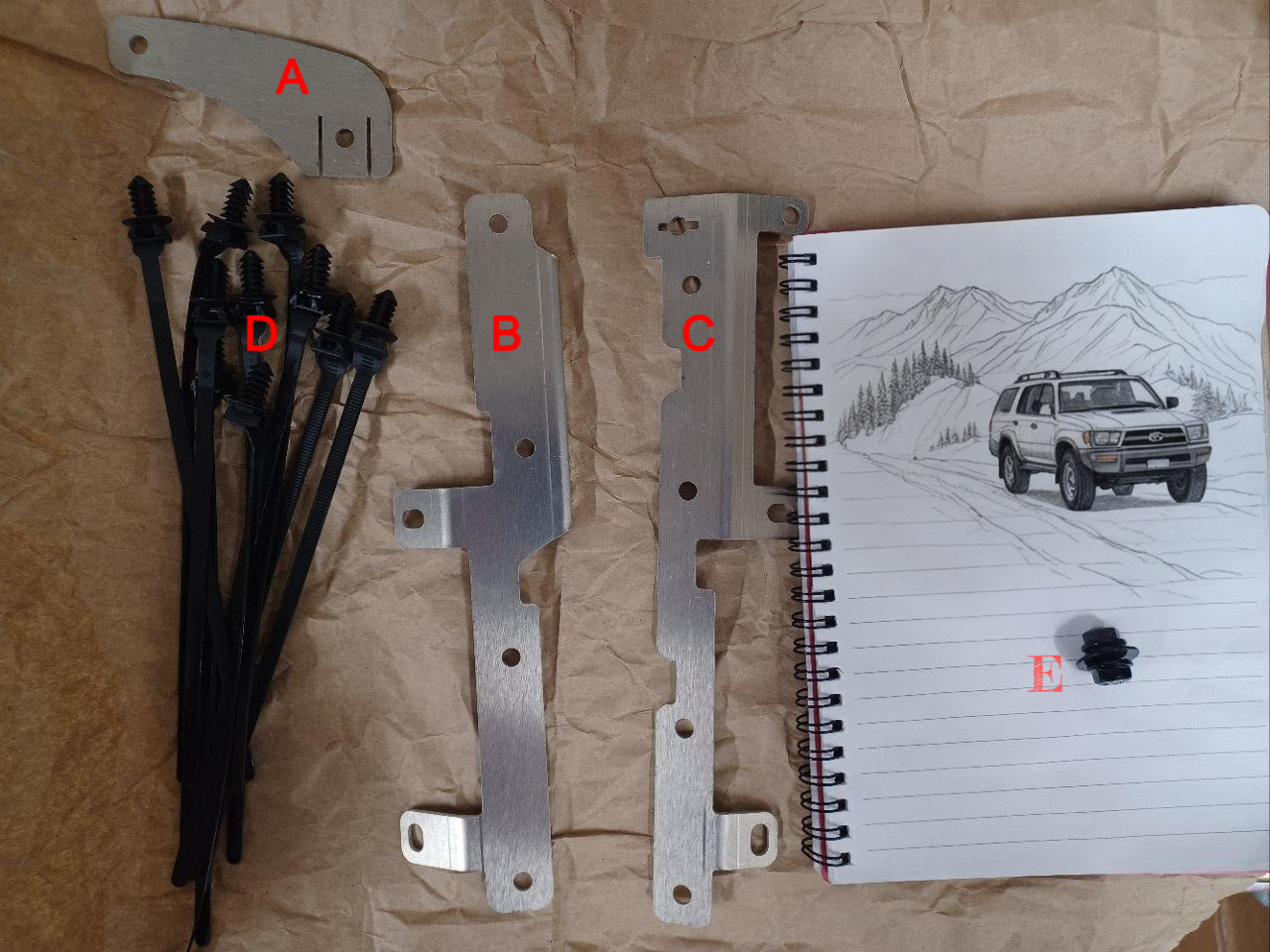
Kit contents — parts A (timing cover bracket), B & C (valve cover brackets), D (push mount zip ties), E (M6 hardware)
Your timing cover bracket kit should include the following items:
- 1x Timing Cover Bracket (A)
- 1x Left Valve Cover Bracket (B)
- 1x Right Valve Cover Bracket (C)
- 10x Push Mount Zip Ties (D)
- 1x M6 Flange Nut, (E)
- 1x M6 Flange Bolt (E)
- 1x M6 Fender Washer (E)
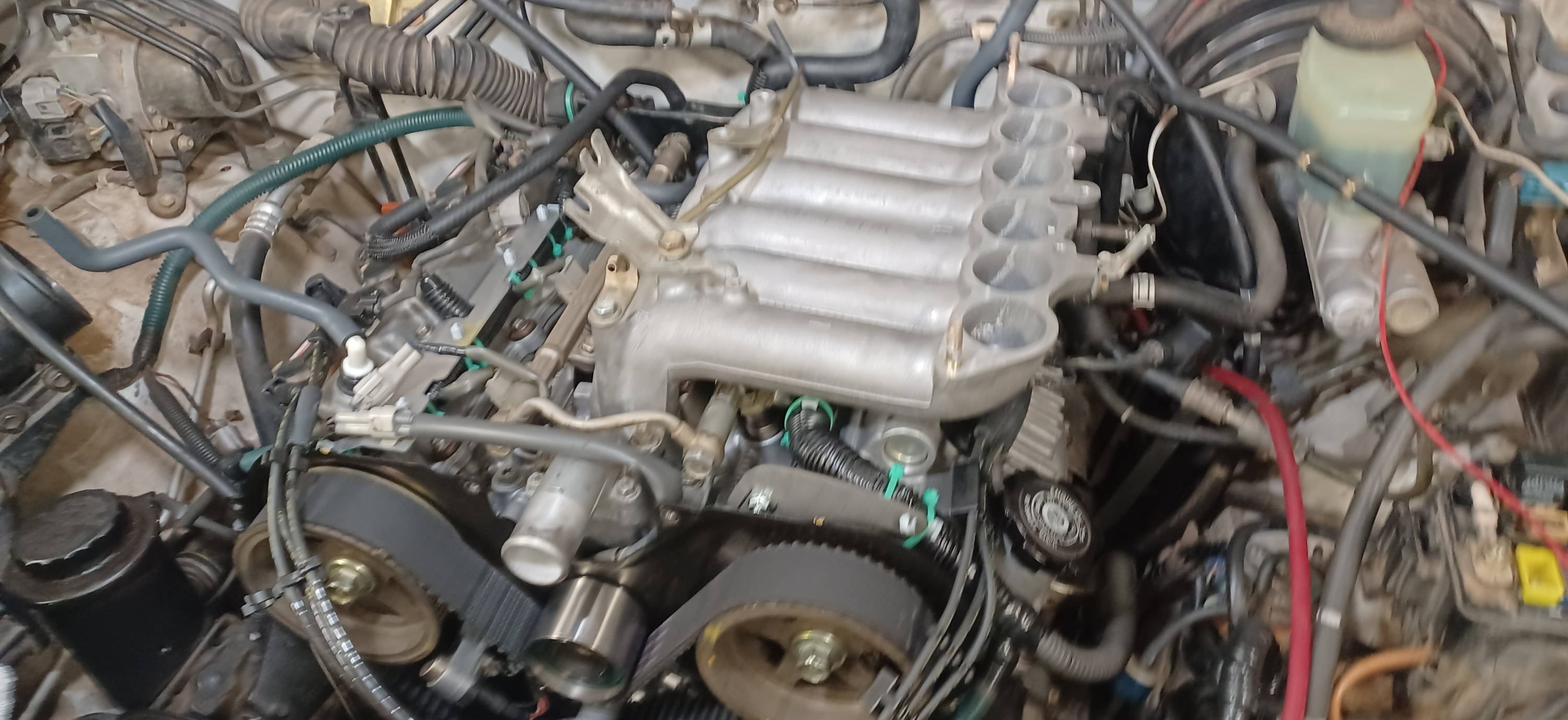
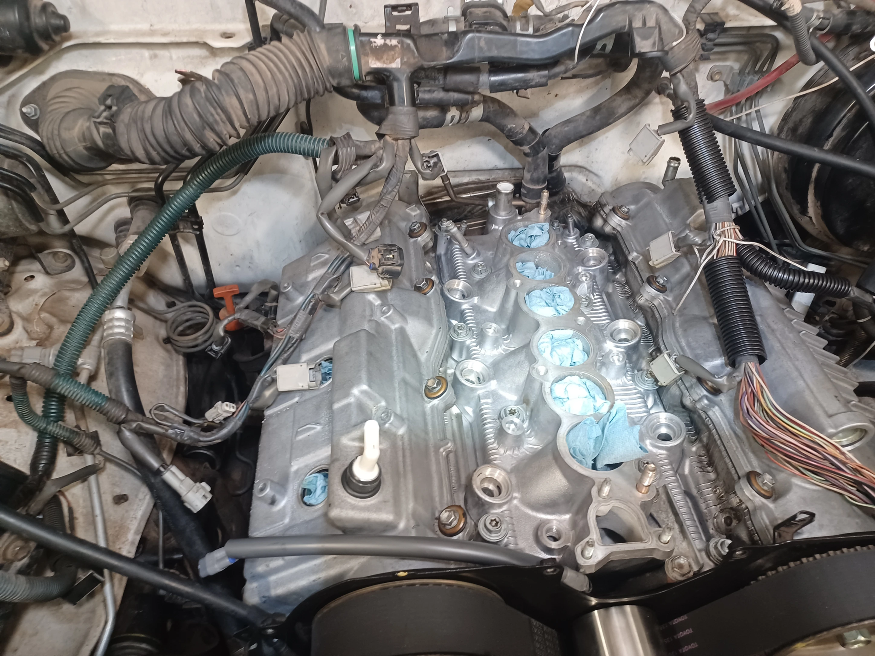
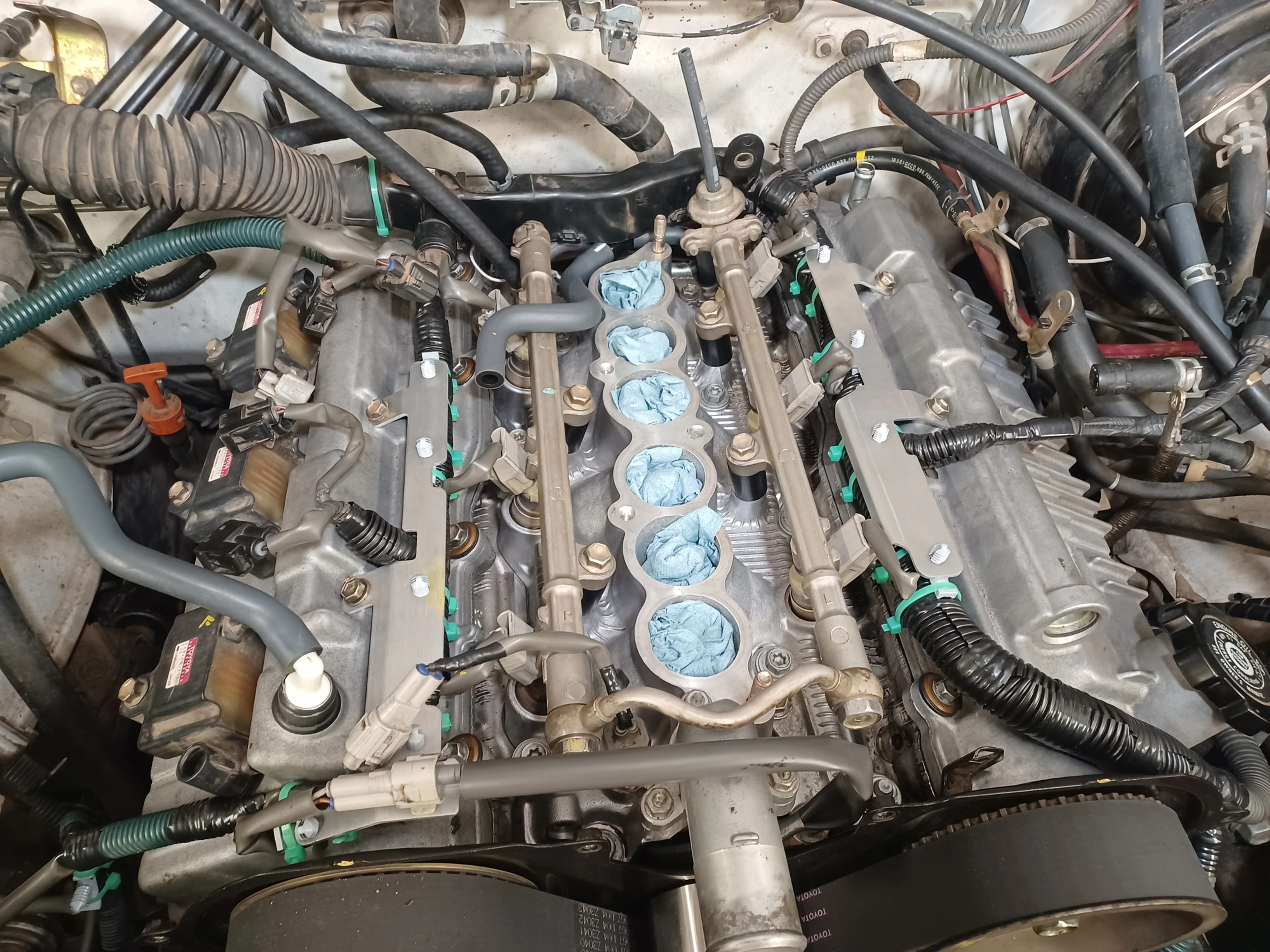
Disassemble the Engine and Expose The Wiring Harness
- Remove the upper intake manifolds, according to the procedure in the Toyota Factory Service Manual.
- Remove the 6 mounting bolts and 4 spark plug wire clamps from the upper timing cover, according to the procedure from the factory service manual.
Note: It is not required to fully remove the timing cover from the engine. Sliding it a few inches back should allow enough access to install the timing cover bracket.
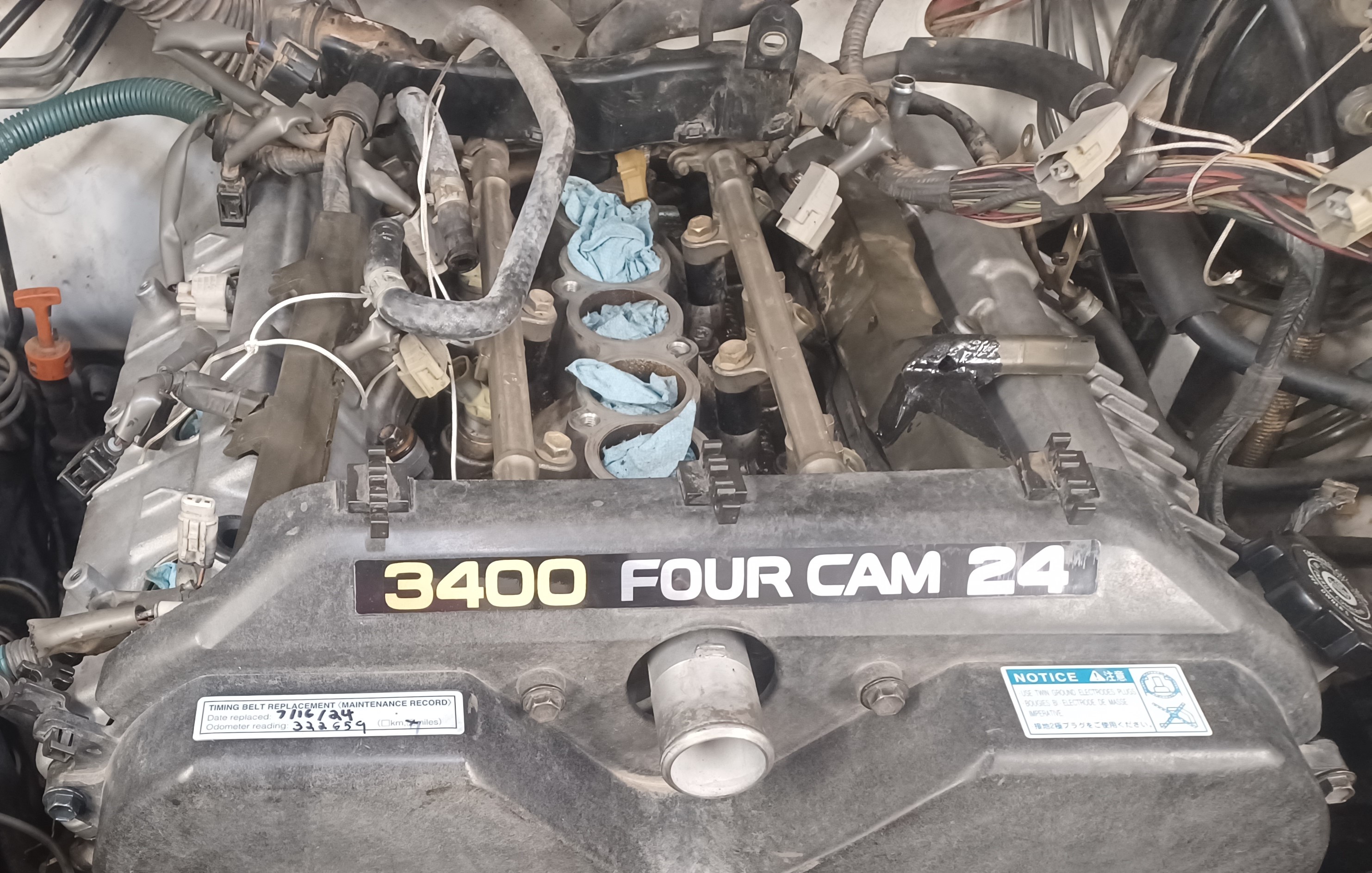
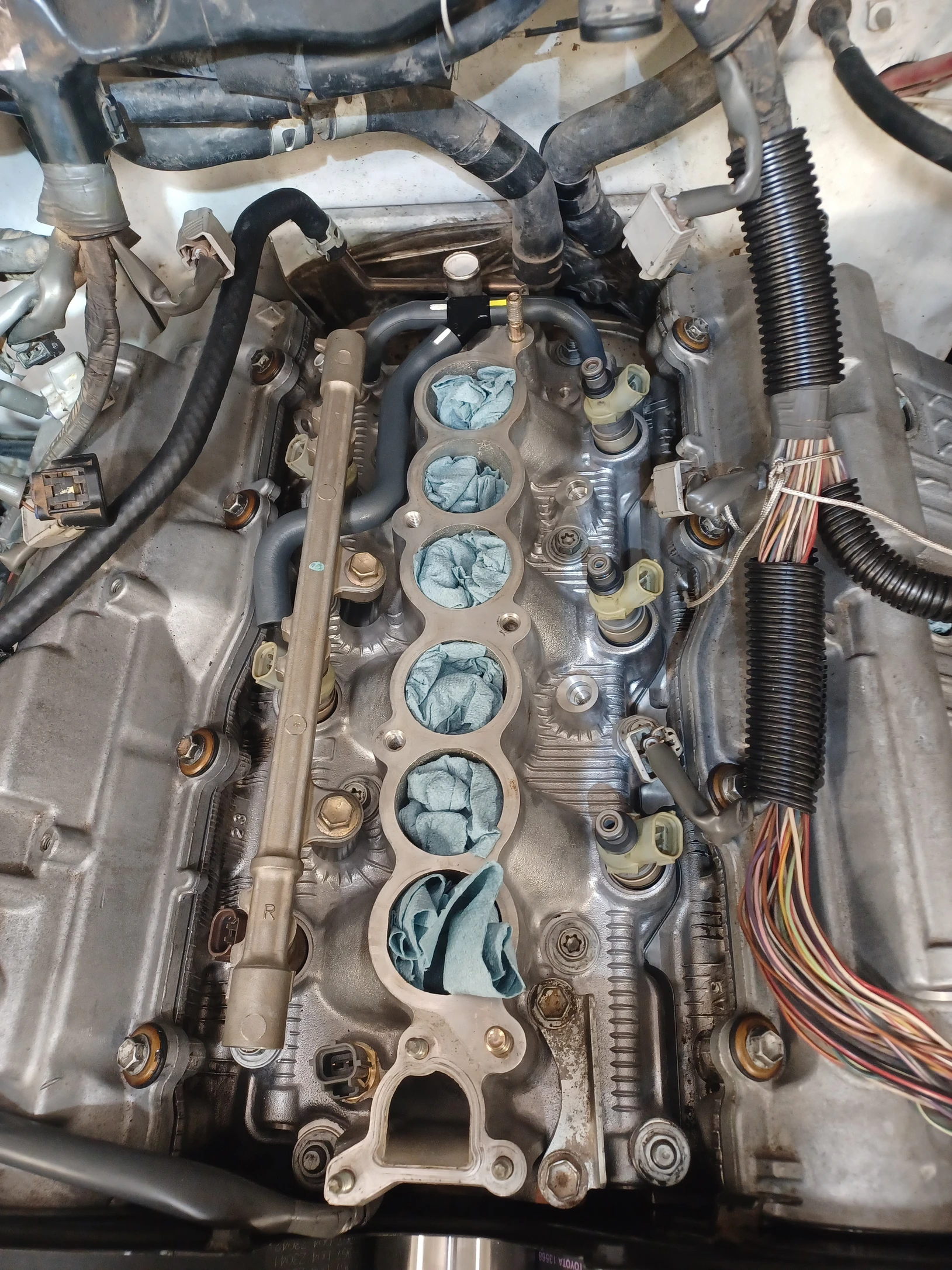
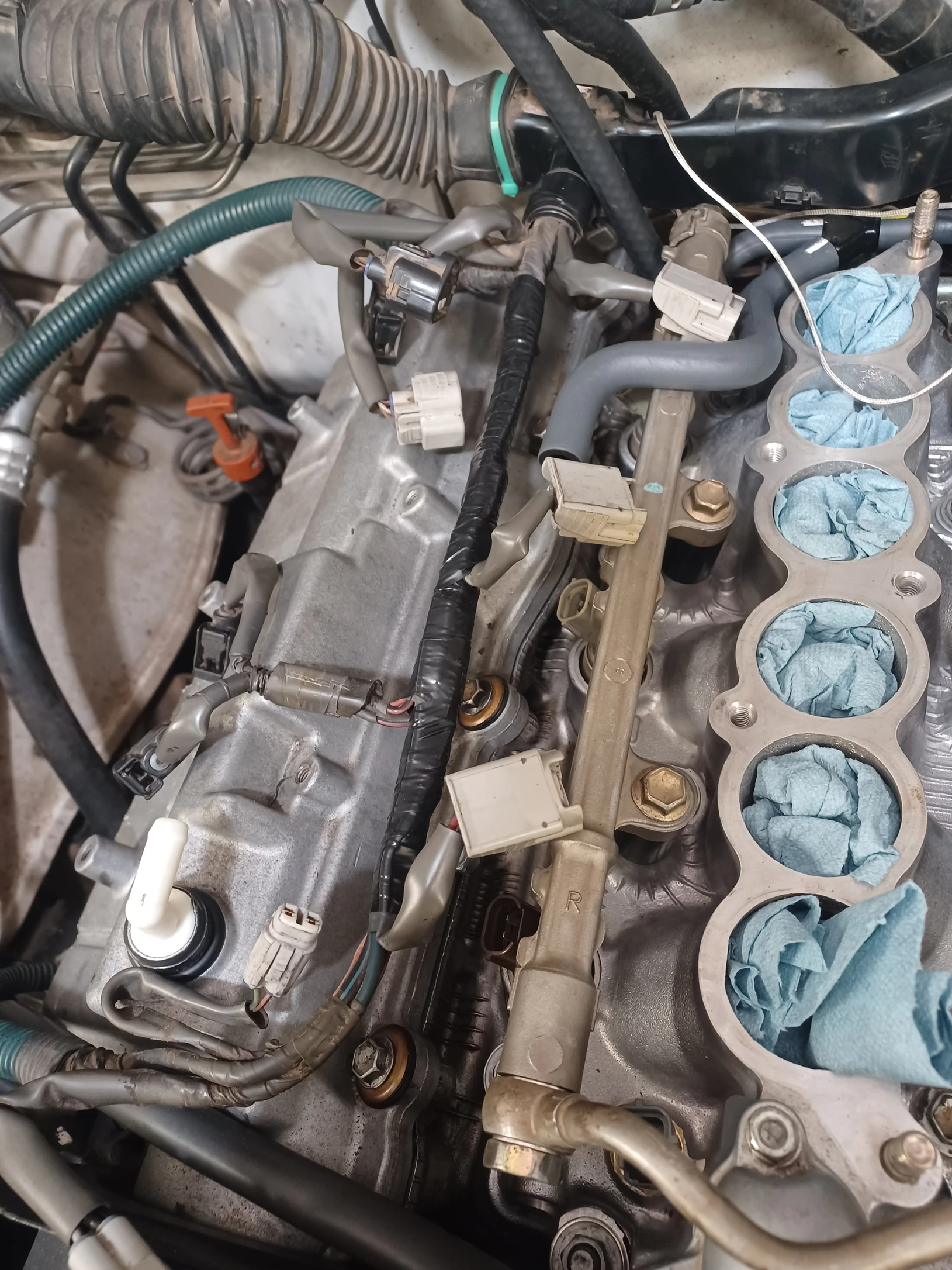
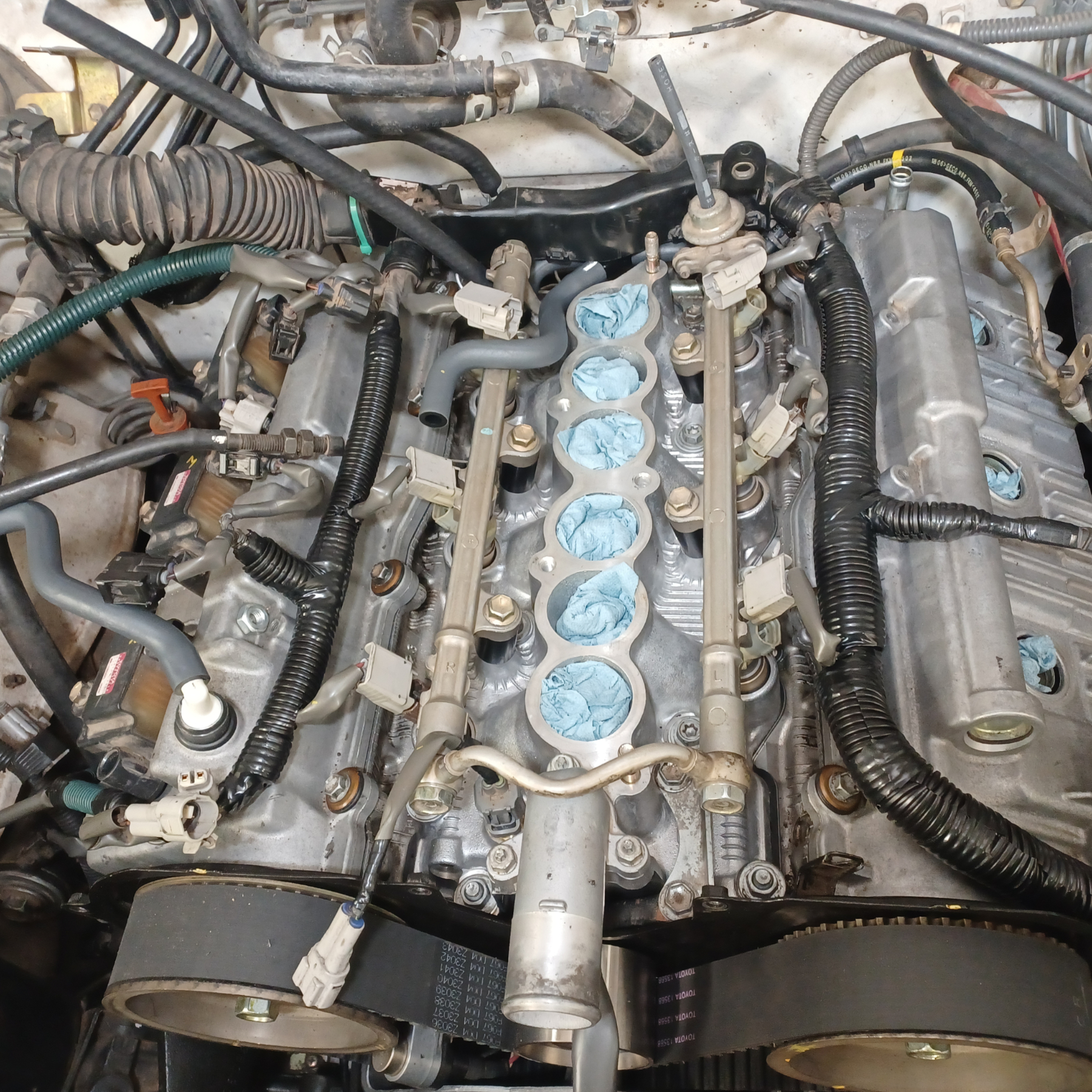
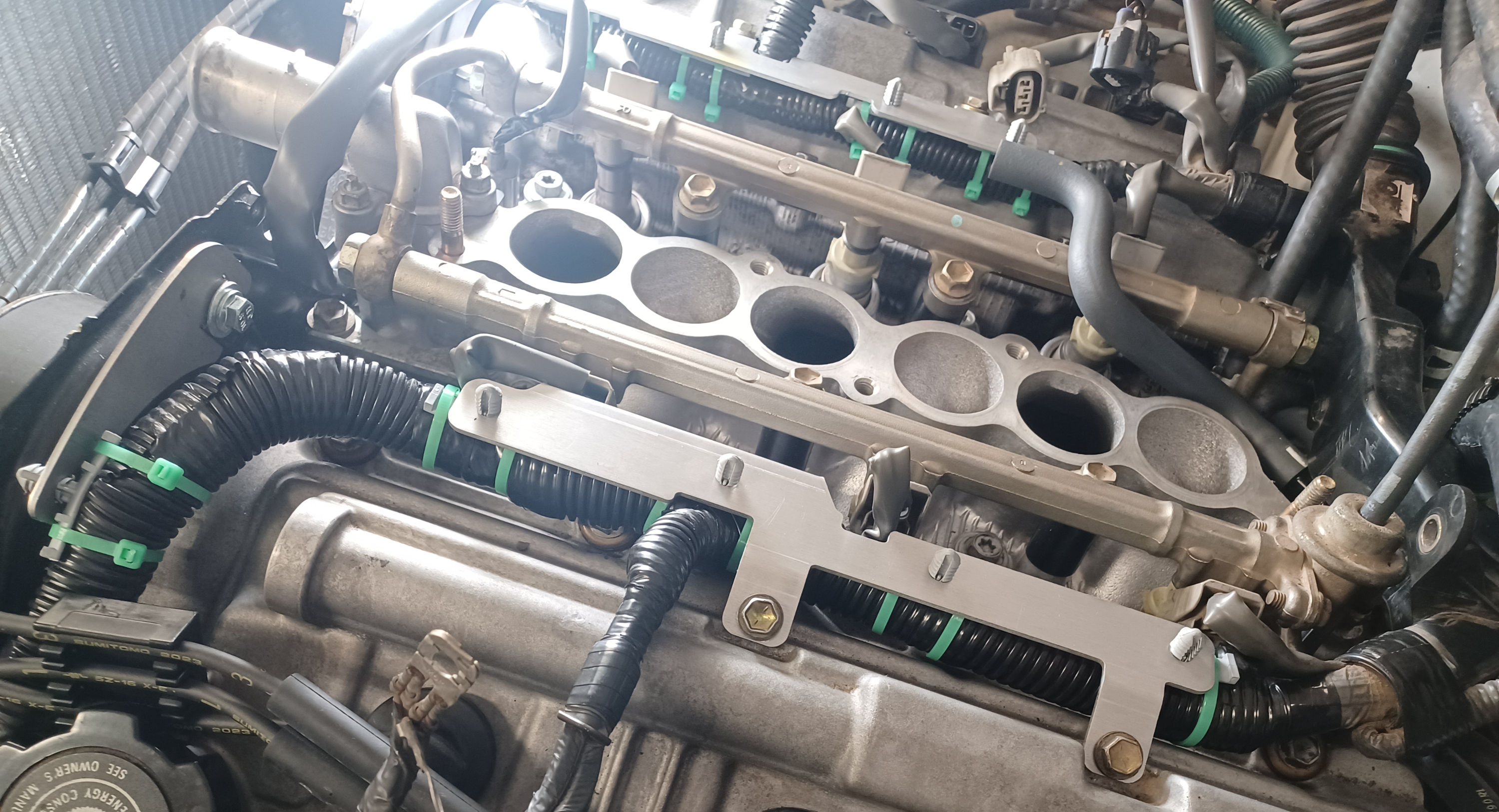
Engine with upper intake removed. Stuff the intake ports with shop towels to keep debris out.
Remove The Original Wiring Harness Covers
- Loosen the rear wiring harness holder by removing the bolt on the driver side, and releasing the mounting tab on the passenger side while pulling up.
- Remove the broken injector harness covers. Typically these can be broken apart by hand. If not, you can break off the tabs that hold the bottom cover.
- Clean any debris and broken pieces from the intake valley.
The original plastic harness covers deteriorate with age and heat — they typically break apart by hand.
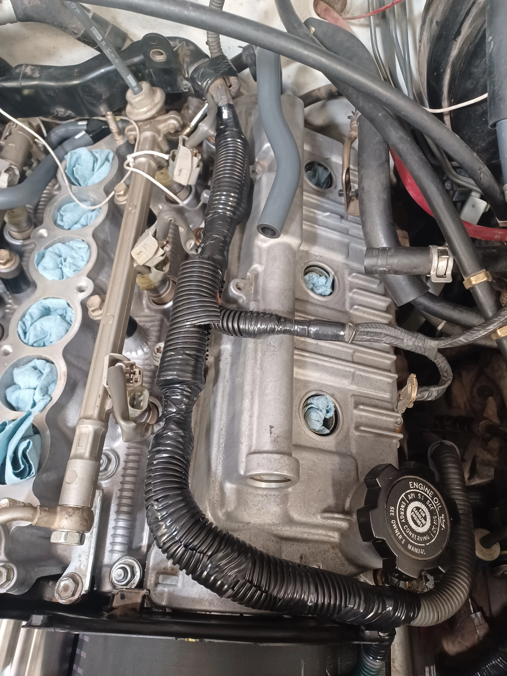
Protect The Wiring
It's strongly recommended to install a protective covering over the wires once the original covers are removed.
- The covering shown in this instruction is made of poly split loom (1/2", 3/8" and 1"), scissor cut to fit the wires. For best results it is recommended to use a high temperature electrical tape such as 3M Super33+
- You may also consider using high heat fabric or silicone wiring harness tape.
Click any image to view full resolution.
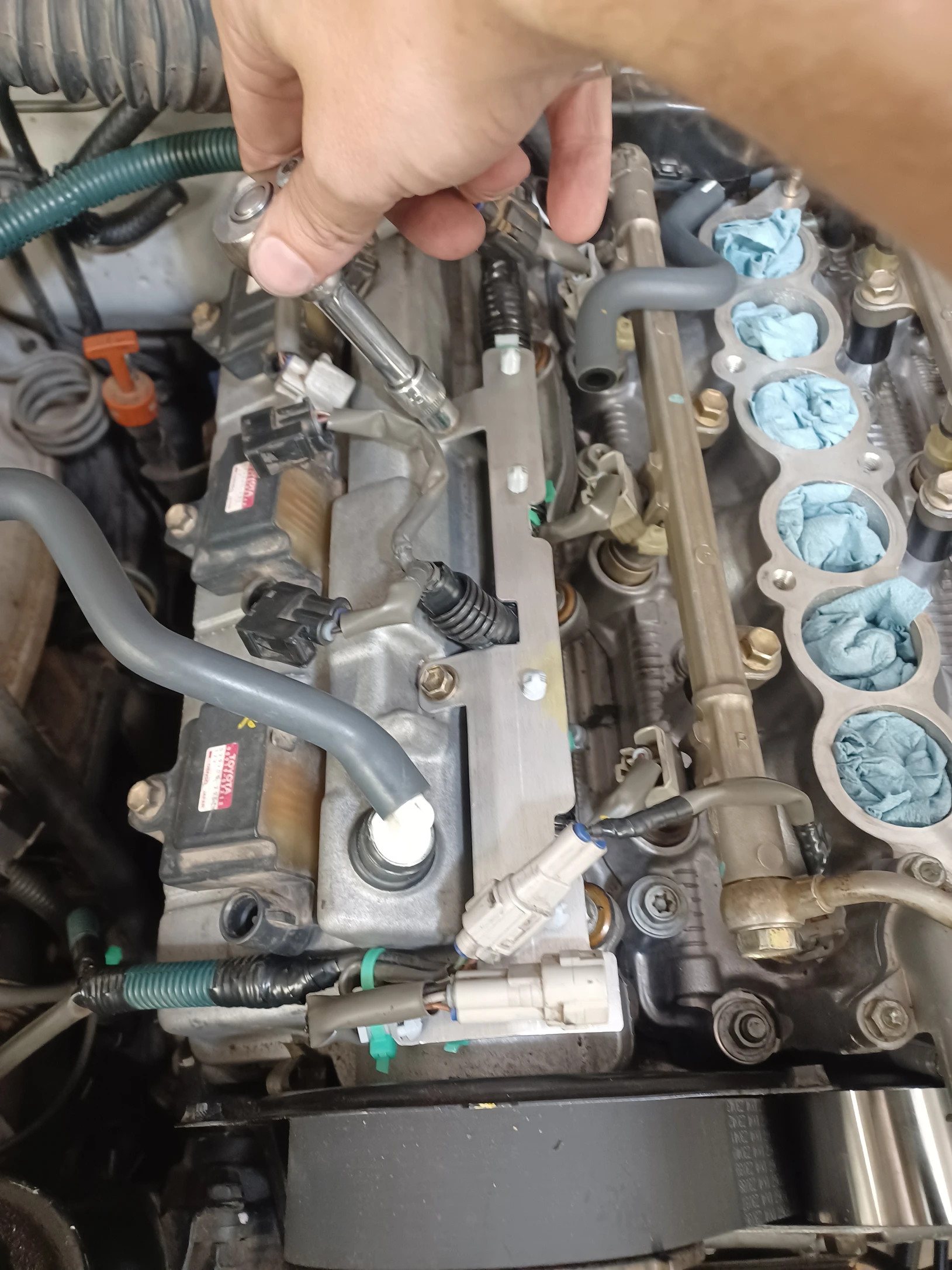
Install The Zip Ties.
- Loosely install 4 zip ties onto each wiring harness as shown above.
- Loosely Install one zip tie after the 90 degree bend of the passenger side wiring harness where the knock sensor and temperature sensor plug reverse directions as shown by the red line.
Zip ties loosely installed on both harnesses — do not tighten yet.
Do not tighten the zip ties yet.
Align Harness Components Before Final Installation
- Starting with the right bracket, place the bracket above the harnesses.
- Align the zip ties with the 4 holes on each bracket.
- Push the mounting post all the way through the brackets. Repeat these steps for the left bracket.
Do not tighten the zip ties yet.
Install the Brackets to the Valve Covers
- Secure the rear wiring loom cover by sliding it onto the passenger side mounting tab, and install the M6 bolt on the driver side.
- Install the wiring brackets to the valve covers with the original 4x M6 bolts. Take care not to overtighten the bolts. (If these bolts are missing you will need to replace them.)
- Carefully adjust the wiring harnesses so there is no tension between the rear harness mounting points and the brackets.
- Clip the plug for the knock sensor harness into the slotted hole on the end of the passenger side bracket.
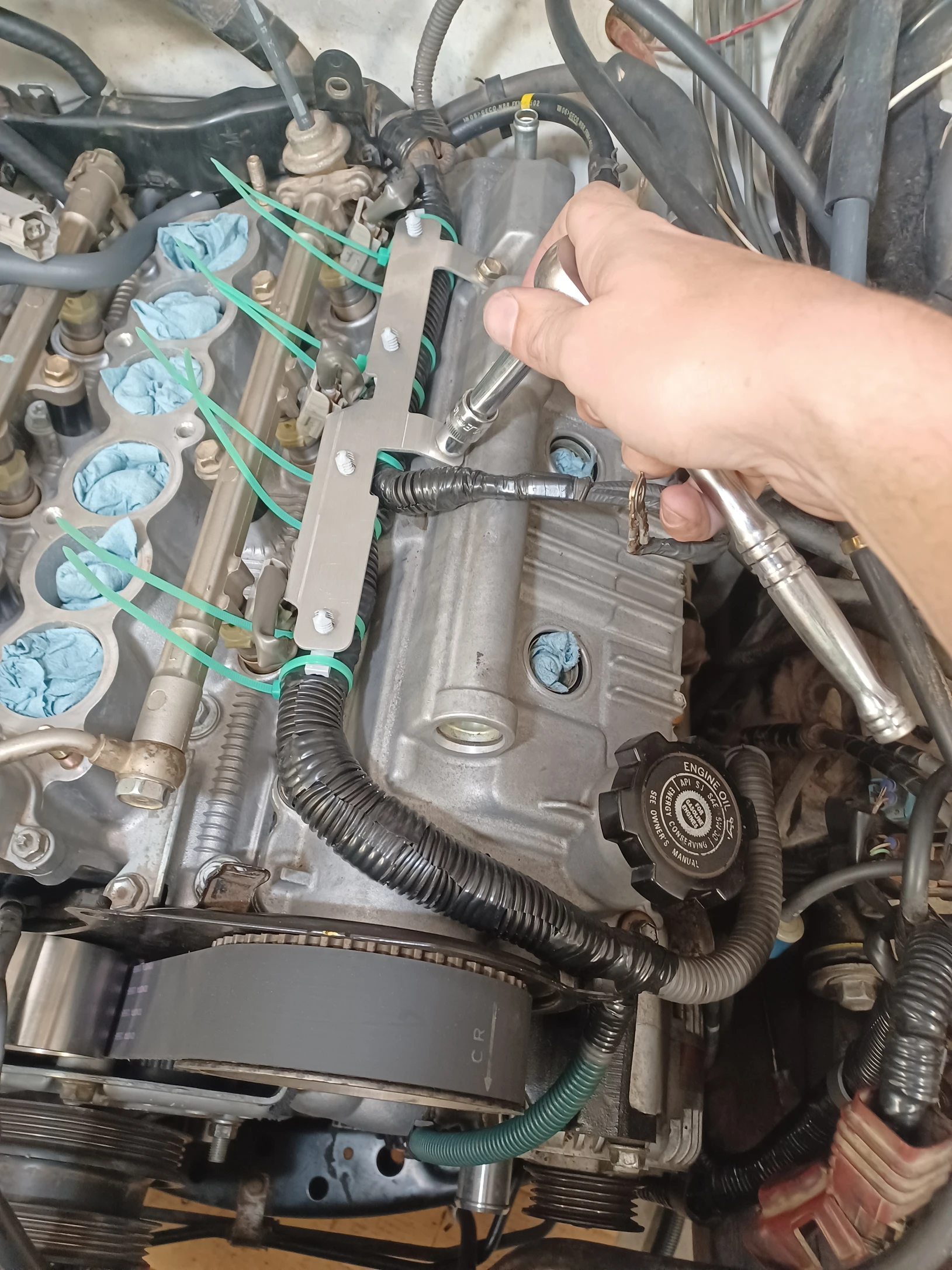
Do not tighten the zip ties yet.
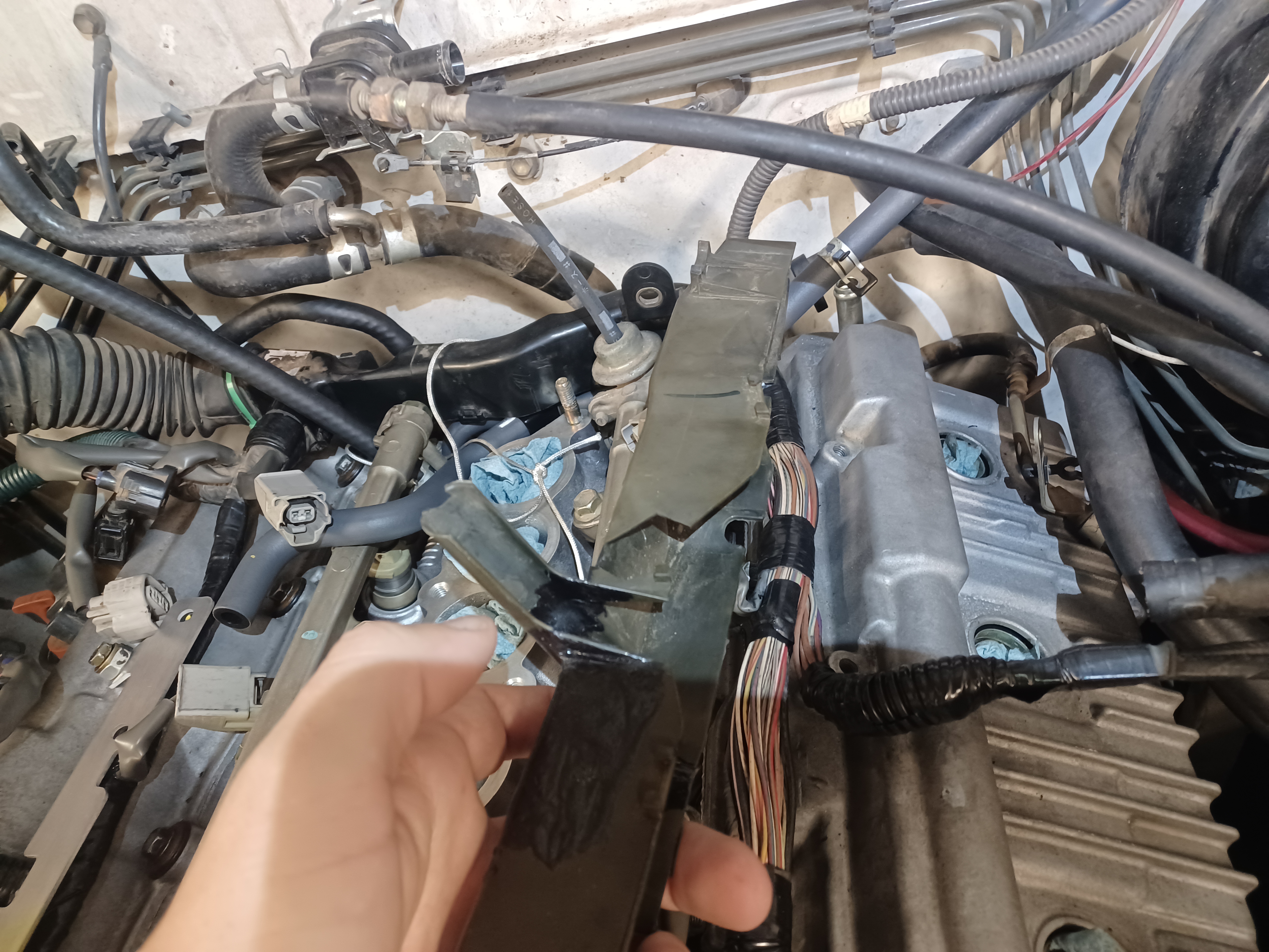
Install The Timing Cover Bracket
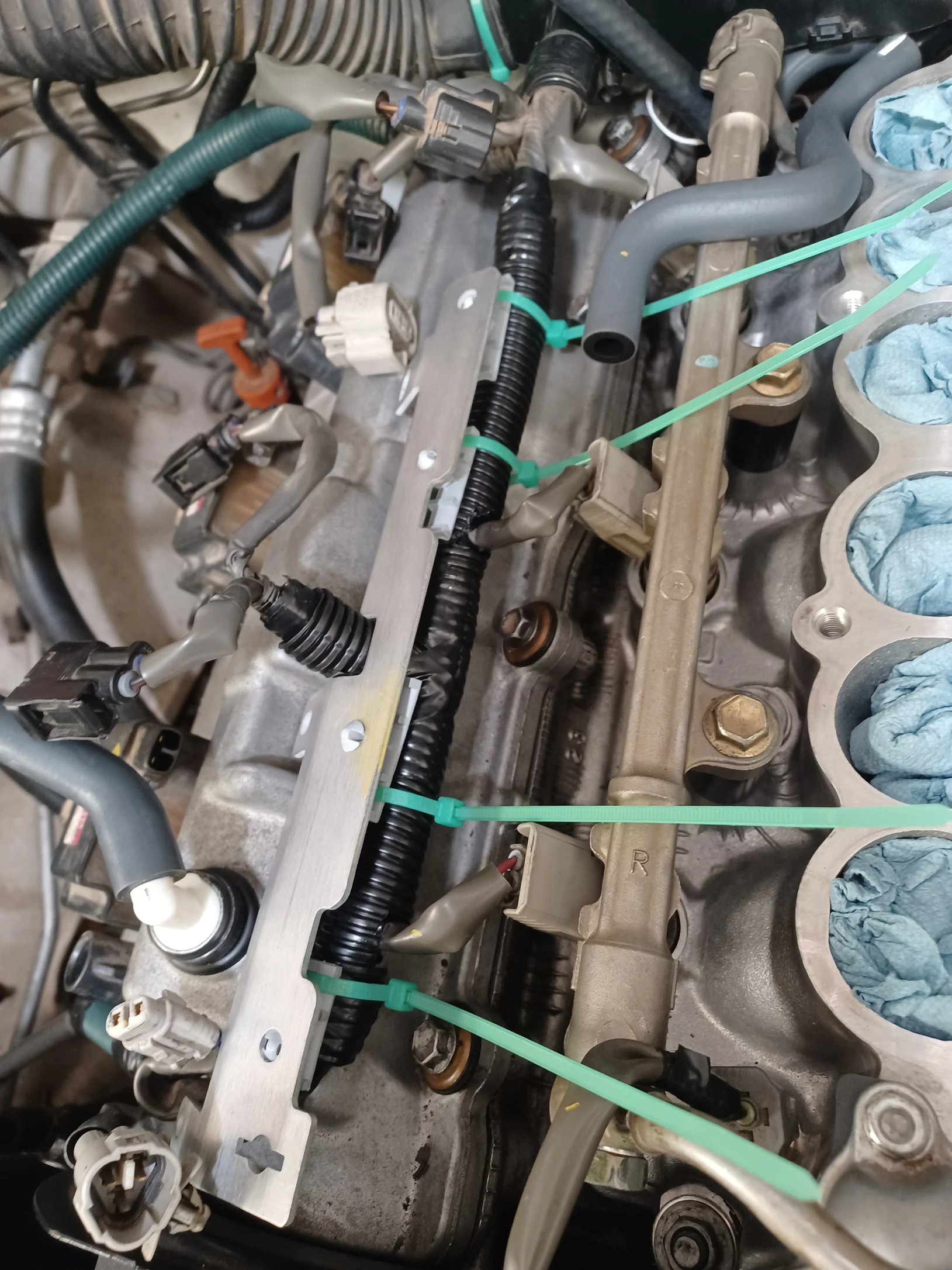
- Take the last zip tie and install it into the hole at the opposite end of the bracket from the slotted tab.
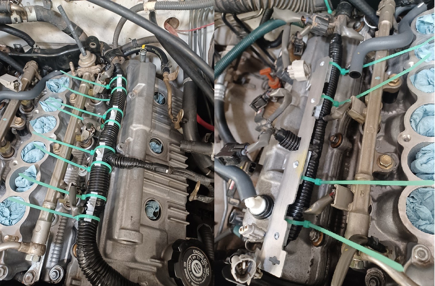
- Place the timing cover bracket behind the sheet metal tab on the back of the rear timing cover as shown in the left image. The slots in the bracket should fit into the tab.
- Using the provided M6 flange bolt and nut, secure the bracket to the rear timing cover.
For best results, the flange bolt should installed with the head towards the front of the engine, and the large washer should be installed between the nut and the timing cover tab.
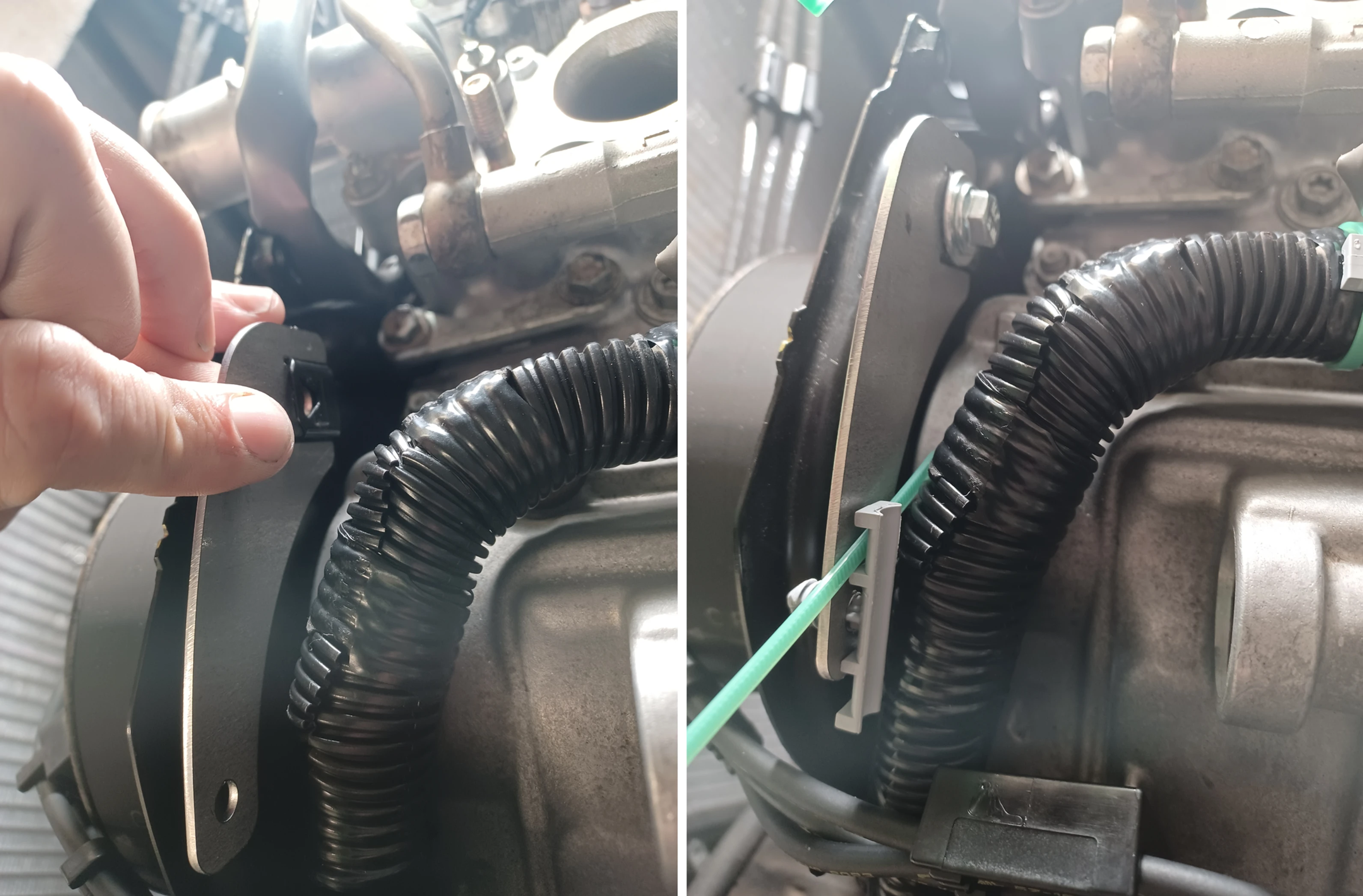
Timing cover bracket area — route the harness and loosely secure with the zip tie before bolting down.
Do not tighten the zip ties yet.
Final Installation
- Check the harnesses to make sure they are free of tension.
- Beginning at the front of the engine, tighten the zip ties and trim off the excess length.
- Clip the knock sensor sub-harness plug into the slotted hole on the passenger side bracket.
Reassemble the engine
- Make sure that all electrical plugs are connected; replace any damaged connectors.
- Replace any damaged vacuum or coolant lines.
- Follow the procedures for reassembly shown in the factory service manual.